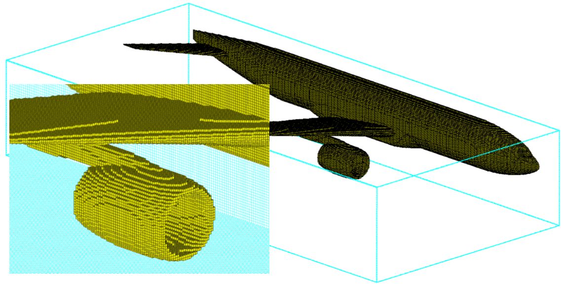
The history of CADfix is an interesting topic that is not familiar to all CADfix users. I thought it worth highlighting one area of extended functionality where CADfix is used to support specialist engineering analysis applications.
CADfix is well established with a global user base where it provides powerful 3D CAD model translation, repair and simplification tools, that enable significant rework reduction as CAD models are exchanged for downstream CAD, CAM and CAE applications. However, it is not commonly known that CADfix started life almost thirty years ago as one of the world’s first commercial general engineering analysis pre- and post-processing solutions, called FAM (an acronym for Field Analysis Modeller).
In addition to the well-known data exchange and geometry repair tools, CADfix CAE (as FAM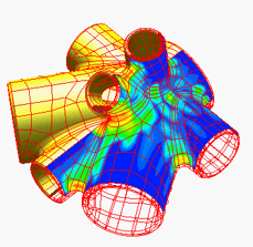 is known today) provides capabilities for meshing, material and physical property definition, constraint and loading definition, and interfaces to analysis packages. Mesh control parameters, properties and boundary conditions are assigned to the CAD geometry, while full associativity and parentage is maintained with the resulting CAE mesh. This is packaged within the highly customisable CADfix CAE graphical user interface and analysis framework with an extensive API.
In fact, CADfix CAE provides a rich tool chest of advanced CAE geometry processing functionality that is drawn upon to support the development of innovative leading edge geometry applications for greater CAD to CAE process automation and integration, such as the geometry handling for CFD analysis in the GHandI project.
CADfix Tartan Meshing
CADfix CAE offers a selection of mesh styles, element types, element quality checks and mesh smoothing options. The mesh styles include:
- Semi-automatic mapped 2D and 3D meshing
- Automatic triangular and tetrahedral meshing
- Finite Difference (Tartan) meshing for structured Cartesian grids
One of the mesh styles available is the strangely named “Tartan” mesher, that generates a mesh often referred to as the “sugar cube” style mesh.
This structured mesh generator uses a 3D lattice definition (also known as IJK directions) to approximate the geometry into regular cells for Finite Difference Time Domain (FDTD) or Transmission Line Method (TLM) solvers, which may be for electromagnetic, mould filling or CFD analysis applications, depending on the equations being solved.
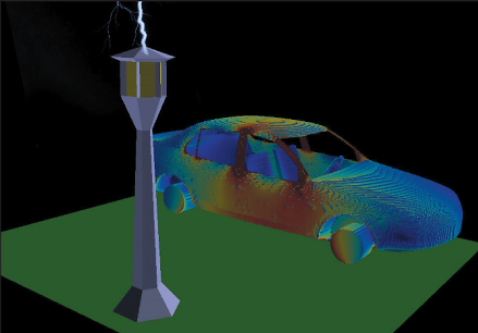 Analysis of lightning strike effects near a vehicle
The CADfix CAE user has full control over the lattice divisions and grading in the I, J and K directions. The divisions may be uniform or non-uniform, and can generate cells that are not necessarily even. This often results in a distinct “Tartan” pattern after which the CADfix mesh style is named (and you thought we just liked plaid).
The CADfix Tartan mesher can be applied to edge, surface and solid geometry to generate a structured mesh consisting of:
- 2D edge elements on edge geometry
- 2D quad face elements on surface geometry
- Rectangular prism elements on solid geometry
Incidentally, we call the resulting CADfix Tartan mesh edge, face and solid cells “twinkles” (because we can!).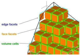
An important aspect is that the edge, face and volume cells all maintain their connectivity with the parent geometry, allowing each level of mesh to be given the physical and material properties of its geometric parent - something that is critical for electromagnetic effect modelling.
The Power of Twinkles
Aside from general speed and robustness, the CADfix Tartan mesher does some serious hard work – it gives users the ability to Tartan mesh open surface models and accurately capture the complex curved surface geometry with 2D cells, something that can be very difficult to do. In addition to the Tartan mesh, CADfix also generates in parallel a smooth Finite Element (FE)-style mesh on the geometry. This enables CADfix to display analysis results contours on the true CAD geometry rather than on the staircase Tartan mesh if required (the results are often easier to consume if they are shown on the real geometry rather than an organised pile of sugar cubes!).
The CADfix Tartan mesher is easy to run. The user simply defines the IJK lattice around the model with the required cell spacing to capture the physical phenomena being modelled and presses the mesh button.
The CADfix API ensures that users can extract the resulting mesh data directly from CADfix for use in their analysis code. The API capability also means that the CADfix Tartan mesher is available as a plug-in for integration with other vendor analysis applications that require a robust and fast Cartesian mesher.
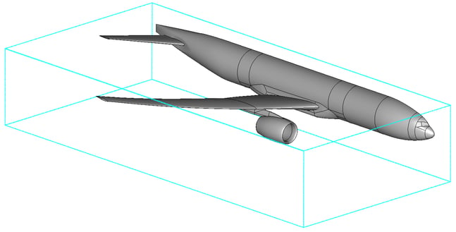 CAD geometry in CADfix with IJK lattice defined
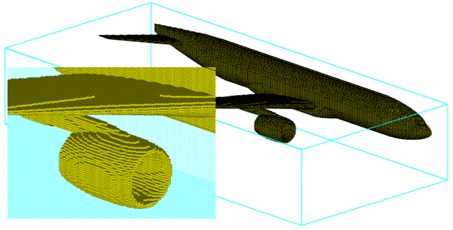 CADfix tartan mesh with zoomed view of Tartan mesh solid cells
Tartan meshing in action
The CADfix Tartan mesher has proven to be a very capable, stable and robust meshing option. When combined with the CADfix geometry handling and mesh-geometry associativity in a customisable analysis framework, it provides an effective specialist pre-processing solution that sits at the heart of some impressive computational analysis work.
Leading international companies including BAE Systems, Saab and Horiba MIRA, use the CADfix Tartan mesher for their electromagnetic analysis applications, often building meshes comprising of several million cells.
Analysis system vendors, including Denver based Electromagnetic Applications, Inc. (EMA), have also implemented CADfix CAE with a customised user interface as a pre- and post- processor for their commercial multi-physics solver suite EMA3D, as described in a new ITI case study.
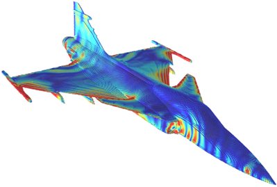 CADfix Tartan mesh of the Saab Gripen with analysis results contours (courtesy of Saab AB)
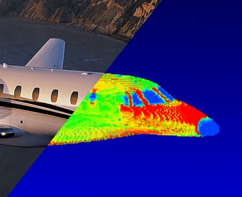
EMA3D lightning simulation with results on the Tartan mesh (courtesy of EMA, Inc.)
I started out in engineering as a CAE engineer building meshes node-by-node and element-by-element, and this helps me appreciate where we are today with the technology and automation available to analysis engineers. As a consequence of our strong CAE history, the CADfix team are all too aware of the demands that analysis engineers and advanced simulation processes place on the suitability of CAD geometry for CAE, and this drives the innovative developments in CADfix today. The knowledge of what is needed when re-using CAD data in downstream meshing applications is one of the things that sets CADfix apart and makes it much more than just a point-to-point translator.
I hope that our existing and potential new CADfix users found this article of interest and that it helps to illustrate the depth of technology that lies behind the CADfix product. I will highlight a few other interesting aspects of CADfix technology and applications in future blog posts.

