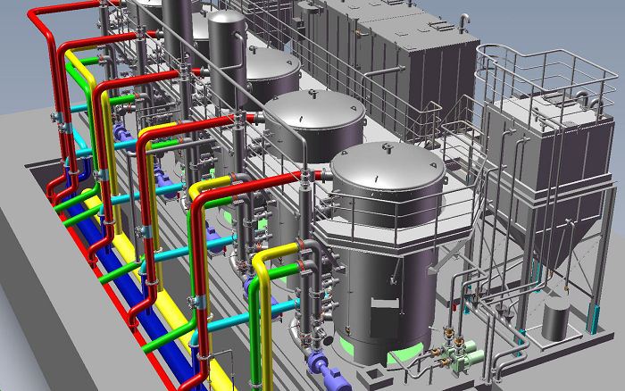
Having spent several years applying CADfix technology to convert, repair and simplify mechanical CAD (MCAD) models for use across diverse CAD, CAM and CAE applications in industries like aerospace, automotive, heavy engineering and consumer goods, I thought I had seen my share of large, complex products and assemblies. Then I saw the dockside construction site of a heavy industry company. The scale of assemblies for the massive tanker sections and offshore rigs was amazing.
The sheer size of the assemblies that need to be modelled for plant and process, offshore and shipbuilding construction is mind-boggling. The large MCAD assemblies I was used to dealing with are often simply a “blob” of equipment, or unwanted noise when integrated within a large plant model! This certainly demonstrates the issues faced by plant designers who need to model the complete plant in a computer aided design system.
 The complete plant model is comprised of superstructure, buildings, pipework, generators, filtration systems, fire safety systems, coolant and lubrication systems, heating, ventilation and air conditioning systems, and a variety of specialist equipment. It’s akin to modelling a small town with the infrastructure required to keep it running for months. Large plant layout models containing a significant number of machines and equipment installations are often so massive that they simply cannot be modelled with the level of detail that we see in traditional MCAD manufacturing models due to the sheer volume of data.
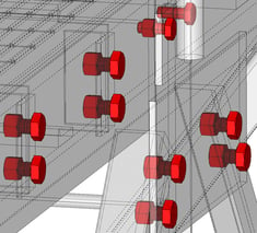 Details like nuts, bolts and screw threads add unnecessary complexity when viewed in the context of a complete plant or offshore installation or ship structure. Design systems used in the plant and process sector tend to define the components using primitive simplified definitions to cope with the data volume. For example, struts, beams, pipes, elbows, connectors, vessels etc, are often just basic solid shape definitions with associated metadata to describe properties such as pipe inner and outer diameters, material and other necessary engineering standards and plant-specific data. This is ideal for the design of the superstructure, layout and pipework etc, and facilitates the representation of massive plant assembly structures. However, issues arise when the plant design engineer needs to integrate MCAD models of large machinery or equipment installations, to accommodate them in the plant layout and perform operations such as clash detection and pipe network routing.
A supplier of machinery and mechanical equipment installations needs to provide models of their hardware to Engineering, Procurement and Construction (EPC) companies for integration with the plant model. This could be a simple pump or motor, HVAC system, or a complex installation housed inside a container or on a skid. These equipment models will typically be modelled with the full MCAD details required for manufacture, and the resulting assemblies can be several hundred Megabytes (MB) or Gigabytes (GB) in size when exported to neutral formats such as STEP, Parasolid, SAT or DWG for delivery. These are often a problem to manage in the MCAD systems themselves, but integration into the plant design system for clash detection and positioning poses a far greater problem.
The plant design system often simply cannot cope with handling large and very detailed MCAD models. When faced with large MCAD assemblies of several hundred MB, users frequently experience excessive load times, import failures, crashes and poor system response. Even if the MCAD assemblies do import OK, the level of detail in the equipment model results is a mass of unintelligible lines in a small area of the overall plant model. Designers often refer to these as “squashed bug” images.
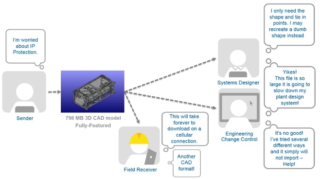
Issues caused by large MCAD models across the plant and process supply chain
Service and construction engineers in the field often need to view plant design data on portable devices and they cannot accept hundreds of MBs of equipment models being downloaded over slow and expensive cellular connections.
The manufacturers who create the data may also need to simplify the MCAD models before distribution, either because they want to protect their intellectual property (IP) investment in the design, or because their contract specifies that they must simplify the data before delivery to the EPC.
ITI has been engaged by companies operating in the plant and process, offshore and shipbuilding industries to help resolve often mission critical issues associated with the import of large MCAD equipment assemblies into plant design systems. For this application “file size is king” and orders of magnitude in file size reduction are demanded to render the MCAD equipment models usable in the plant design system, whilst maintaining the required information for plant integration.
The established CADfix technology has been applied to the problems faced by process and plant engineers and features a new CADfix advanced automatic simplification Wizard supported by dedicated manual simplification tools, targeted at tackling data reduction. The CADfix tools allow the plant designer to quickly and easily:
- Remove unwanted small parts such as nuts, bolts, washers and other small solids
- Remove small CAD features such as holes, protrusions, fillets, logos, lettering, ribs
- Remove invisible internal parts
- Simplify complex parts to basic shapes such as cylinders and bounding boxes
The CADfix automatic simplification Wizard takes fully featured MCAD models and automatically removes details and simplifies parts to basic geometric forms.
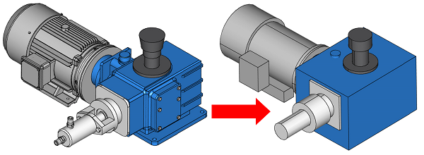
Motor assembly reduced from 6MB to 140KB in less than thirty seconds.
Massive data savings can also be achieved by automatically removing unwanted detail that is effectively hidden within a container or building and invisible to the rest of the plant.

Automatic hidden internal detail removal leads to significant file size reductions.
ITI’s CADfix solution for plant and process is designed to achieve as much model simplification and data reduction as possible, whilst retaining the outer envelope of the MCAD model for clash detection and pipe routing, with the important features, key locating points and interfaces to the rest of the plant. We have demonstrated that it is possible to quickly remove unwanted parts and features, and simplify other parts, to enable the seamless incorporation of MCAD equipment models into the overall plant layout.
This image below demonstrates possible data reduction for complex MCAD equipment models, where an original 40MB DWG MCAD model with 73K CAD faces is reduced to a 1MB DWG with only 2K CAD faces. This 97% data reduction was achieved in just 15 minutes.
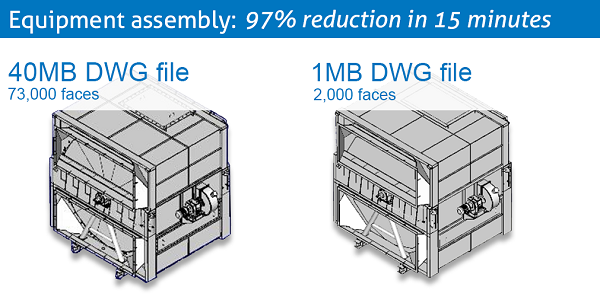
40MB DWG file reduced to 1MB in 15 minutes
Further examples include:
- Stairway and platform assembly: reduced from a 72MB SAT file to 5MB in 20 minutes
- Large equipment assembly: reduced from a 37MB DWG file to 4MB in 25 minutes
- Large skid assembly: reduced from a 798MB STEP file to 29MB in 30 minutes
The potential impact on the whole plant assembly is massive. The removal or simplification of geometry and small parts across hundreds or thousands of components will facilitate the removal of GB of data across the plant model, and MCAD equipment integration times can be measured in hours rather than days or weeks.
ITI now regularly deploys the CADfix model simplification technology to help plant and process designers achieve some amazing data reductions and streamline engineering processes. By applying the CADfix technology for MCAD model simplification, orders of magnitude in file size reduction can be achieved ahead of integration of the models into 3D plant and process design systems, saving days of non-productive geometry handling and increasing design efficiency. Most importantly, it enables companies to complete projects, get to commissioning faster, and realise commercial bonuses and increased profit margins.
For a limited time ITI is offering a free eval of CADfix PPS, learn more here.

