
Mesh generation is still a bottleneck in the simulation pipeline. The NASA Vision 2030 study [1] reports that “significant human intervention is often required,” whereas “ultimately the mesh generation process should be invisible to the … engineer.” Mesh sizing plays a significant part in this:
- Setting up sizing can be a time-consuming process
- Incorrect or incompatible sizing can lead to meshing failures or unusable meshes
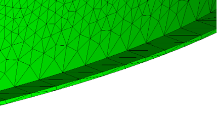
Figure 1: Poor triangle quality caused by incorrect sizing across narrow feature.
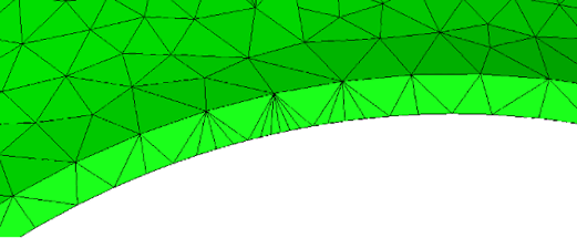
Figure 2: Poor triangle quality caused mismatched sizing across narrow feature.
In typical industrial practise, the user is responsible for specifying element lengths on edges, faces, or through a volume. These can be assignments on geometry, or sometimes using sources, RBFs, or another volumetric framework. We call this imperative sizing: the element sizes are specified directly by the user.
However, sizing guides given to engineers don’t look like this. They state characteristics of a good mesh, for instance:
- “8 points across the trailing edge”
- “At least two elements through the thickness”
- “16 points around the diameter”
- “Maximum length ratio of 1.2:1”
This is declarative sizing: it specifies the constraints the sizing must satisfy. We have been developing a rule-based mesh density field to allow us to use this more natural method of specifying mesh sizing, to reduce the time taken to build a fit-for-purpose mesh. This uses sizing rules to generate a density field described as a metric tensor [2], on which we deploy a selection of metric-sensitive mesh generators. Users can freely mix a wide range of sizing rules, including:
- Minimum/maximum element length
- Sag: maximum distance between geometry and mesh
- Turn: maximum normal vector deviation across an element
- Cross-edge sag and turn for isotropic meshing
- Proximity: minimum number of elements across a face
- Maximum element length ratio
- Manual or automatic mesh sizing sources for imperative control
Two sizing rules are worth examining more closely: proximity, and maximum length ratio. Proximity sizing uses the 2D medial axis to determine the local face thickness, and calculate an appropriate element size to get the desired number of elements across the face.
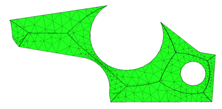 Figure 3: Example face with medial axis and 3 elements across face.
Maximum length ratio enforces smoothness in the sizing field, specifying how rapidly sizes can grow or shrink. This is particularly important when enforcing consistency of sizing across a narrow feature, or between two neighboring meshes.
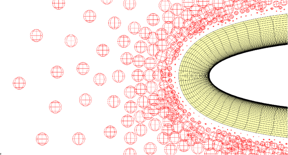
Figure 4: An unconstrained sizing field neighboring a structured mesh. The sizes are forced to match at the boundary. The circles represent the expected element sizes in the mesh.
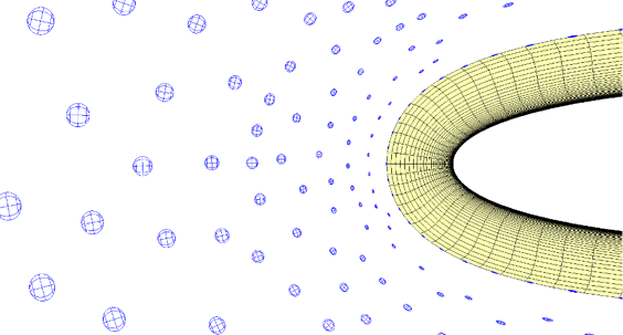
Figure 5: The same sizing field with a maximum ratio rule applied. Notice the boundary influence is propagated smoothly into the sizing field.
We show two examples. The first is an aero engine casing, similar to a customer geometry. We have meshed it using isotropic triangles, and in the customer case also generated a tetrahedral volume mesh. Sizing was specified as:
- Maximum element length: 25mm
- Sag: 0.5mm
- Turn: 30 degrees
- Proximity: min. 2 elements through thickness
- Maximum length ratio: 1.2:1.
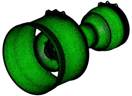
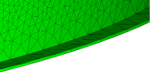
Figure 6: An overview of the mesh, 12.1 million triangle elements.
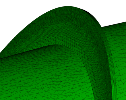
Figure 7: Mesh on stiffening ring shows proximity sizing and maximum length ratio propagation.
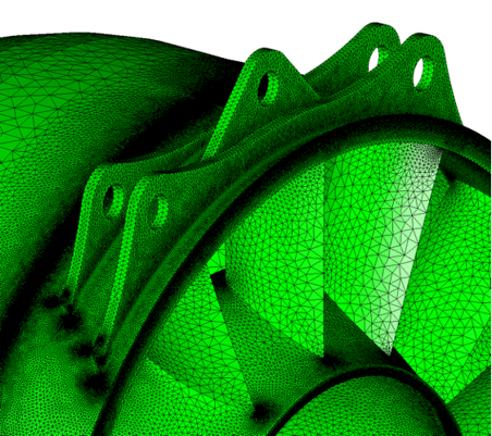
Figure 8: Mesh on engine mounts shows proximity sizing.
The second example is an aircraft geometry, from the AIAA drag prediction workshop [3]. This was meshed using our new anisotropic quad-dominant mesher. Sizing was specified as:
- Maximum length: 0.5in
- Minimum length: 0.1in
- Sag: 0.1295in
- Turn: 10 degrees
- Maximum length ratio: 1.2:1
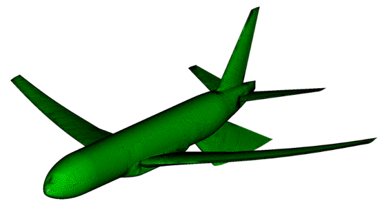
Figure 9: Quad-dominant surface mesh on the NASA common research model.
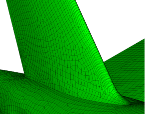
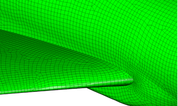
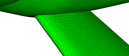
Figure 10-12: Close-up views showing well-aligned higher aspect ratio elements automatically placed along the highly curved sections.
In conclusion, we have shown that mesh generation can be declarative. Instead of specifying sizes directly, we can specify the rules that a mesh must satisfy. These rules can be non-trivial, including quantities such as proximity and growth rate, and produce a consistent sizing field. Metric-sensitive mesh generators can be used on these sizing fields to create robust, high quality isotropic or anisotropic meshes for FEA or CFD.
References
|
[1] |
NASA, “CFD Vision 2030 Study: A Path to Revolutionary Computational Aerosciences,” NASA CR-2014-218178, 2014. |
|
[2] |
A. Loseille and F. Alzauzet, “Continuous Mesh Framework Part I: Well-Posed Continuous Interpolation Error,” SIAM Journal on Numerical Analysis, vol. 49, no. 1, pp. 30-60, 2011. |
|
[3] |
J. Vassberg, M. DeHaan, S. Rivers and R. Wahls, “Development of a Common Research Model,” in AIAA, 2008. |