CAE simulation is an integral part of product design – if the right questions are asked, a simulation run can tell you whether your product is fit for purpose, efficient, manufacturable etc. etc. The meshing process discretizes CAD models (points, edges, faces, bodies) to make it suitable for simulation.
CAD models consist of topology and geometry, essentially a collection of bounded shapes such as NURBS which enclose a finite volume. In the context of simulation, the problem is often that the boundaries of these shapes (i.e. the edges) are often useless. They are there purely to mark the transition from one shape (or CAD surface) to another.
A good quality mesh should capture the geometric features of interest at the appropriate level of detail for an accurate simulation, and not be restricted or constrained by the topology of the CAD model. For example, the CAD edge between a cylindrical fillet and an adjacent plane exists purely to mark the transition from the cylinder to the plane. If we don’t care about the change in curvature for our simulation, then that boundary edge is "useless" and there is no need to place mesh nodes on it.
On the other hand, if we care about curvature because it impacts the physical phenomena that we want to simulate, then the edge is an important feature that needs to be captured in the mesh, because it clearly marks the transition in curvature as we walk from the planar surface to the cylindrical blend. The identification of such internal topological edges and pretending that they do not exist is known as Virtual Topology. In the meshing context, it allows us to capture the geometry for our simulation rather than the topology. However, this is tricky. How do we seamlessly walk from one shape to another, without any knowledge of where the boundaries are, while staying faithful to the original geometry that we want to simulate?
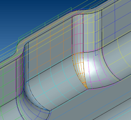
At ITI, we have developed a very robust method of achieving exactly that, with the CADfix “as-rigid-as-possible” (ARAP) parameterization of regions within a model. We automatically create a single valid parameter space for a complex collection of CAD faces, i.e. every point on that collection of faces can be uniquely mapped onto the CADfix ARAP parameter space and vice versa (i.e., bijective). The image shows the continuous isolines of the CADfix ARAP parameter space spanning several faces.
This is exactly the technology that allows us to walk over internal face boundary edges as if they do not exist. This parameter space is multi-purpose. It can be used to evaluate coordinates, derivatives, curvatures etc. as required to perform robust geometry processing and meshing operations.
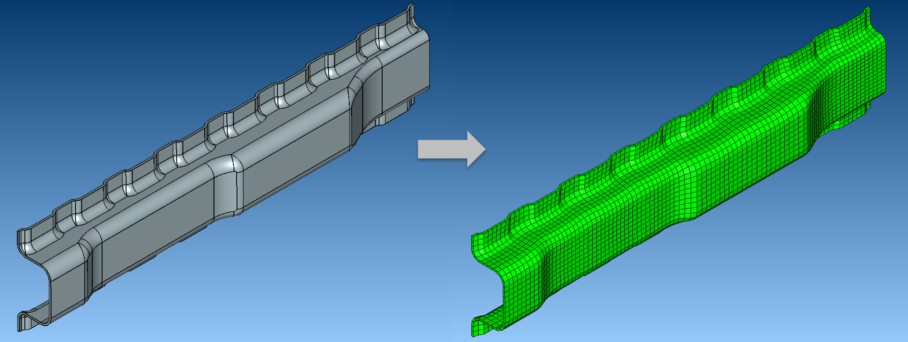
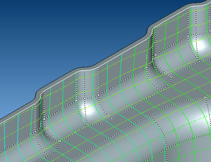
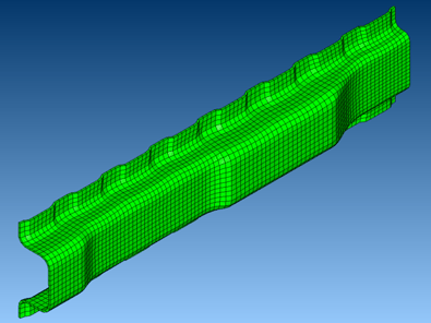
In the simple example shown, we perform Transfinite Interpolation within the CADfix ARAP parameter space and evaluate the positions of the mesh in 3D, resulting in the ability for us to create a highly structured Hexahedral mesh of the part, without the mesh being constrained by the internal face boundary edges.
So, what is the real benefit of capturing the geometry rather than topology in the mesh, and what difference does it make?
Primarily, the edge topology of the model can add unnecessary constraints on the mesh, and that can cause the solver to focus on the "wrong" things. For example, imagine you have a complex model to run some simulations on, and the model contains a very short edge. For the purposes of your simulation, that short edge might be geometrically useless and is there purely to mark the transition from one shape to another, or it may be an unwanted modelling artefact from the source CAD system.
If we mesh the topology, we will generate a lot of small elements and a high mesh density around the short edge. This means the solver will spend a long time trying to analyse the physics around that short edge since the mesh around it is so dense - but we don't care about that short edge, and it has no impact on the physical problem that we are trying to simulate. Trying to mesh that edge can lead to poor a quality mesh that impacts simulation fidelity, and an overly dense mesh that can have a significant impact on simulation time with an analysis running for days instead of minutes/hours.
However, if we make use of Virtual Topology and mesh the geometry instead, that short edge will be invisible to the mesher (since it contributes nothing to the description of the shape of your model). The mesh is no longer constrained by the short edge, the mesh quality is improved, and the solver will be able to focus on the areas where the interesting physics is happening.