Introduction: Simulating the complex flow physics at a blade/wall junction often requires very specific mesh generation to capture the complex secondary flow features reliably. On top of the complex physics, these junctions are often where you will find some of the most challenging geometry, such as tightly curved fillet surfaces, variable radius blends, sliver edges and faces, and highly raked leading and trailing edges. A manual structured multi-block approach is often the preferred meshing strategy as it allows the mesh topology to be separated from the CAD topology, with the final structured mesh just projected to the CAD geometry as a final stage. In this article, we will describe significant progress the CADfix team has made towards generating these high-quality structured junction meshes automatically. The solution leverages multiple novel technologies unique to CADfix.
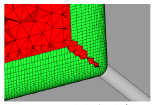
Mesh generation for CFD can be automated with an advancing front technique. A surface mesh is extruded in layers normal to the surface to form a boundary layer volume mesh; however, conflicts can arise in the corners of the air volume. The mesh fronts collide and cause layer stopping or layer height reduction, resulting in the farfield tetrahedral elements encroaching into the boundary layer mesh, and poor-quality mesh unsuitable for capturing the modeled physics. The surface meshes can also be affected by sliver faces and fractured surface patches in the CAD model, both of which are common near chains of fillets.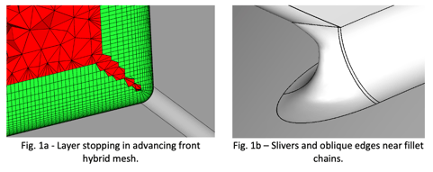 Partitioning: CADfix Geometric Reasoning (GR) based on the Medial Object (MO) offers a way to directly compute the location of the front collisions and to build a set of conformal partitions that divide up the fluid domain.
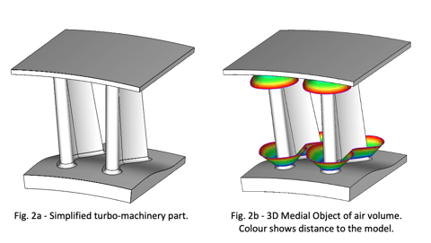
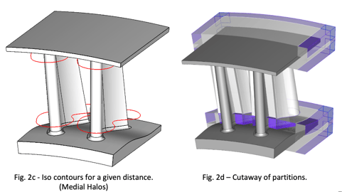 Fig. 2b shows the medial object, composed of all points equidistant from two locations on the defining model. A user-specified distance, the only user input required by the automatic process, is used to control the depth of the structured mesh. Medial halos are constructed at this distance (Fig. 2c).
Partitions are automatically created as B-rep solids from the halos and other construction geometry (Fig. 2d).
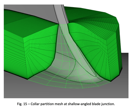
Each partition can then be meshed using an appropriate structured or unstructured method. The recent addition of collar partitions eases the creation of structured mesh near fillets and makes the partitioning less sensitive to the layout of surface patches in the CAD model.
Collar partitions are built across the skin of the input model beneath the medial halos, stepping over the fillet faces and other inconvenient CAD geometry detail. The collar partitions are divided up along their length to make conformal interfaces with adjoining partitions. These partitions are present in Fig. 2d and shown more clearly in Fig. 3.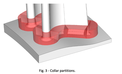 Where each partition dividing wall rests on the model’s surface, a line is traced across the surface to connect the endpoints of the two uprights. Where the partitions make contact with the model surface, the structured mesh can be generated, independent of the face boundaries. The collar partitions are three-sided prisms by construction, lending themselves well to sweep meshing.
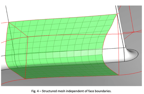
 The complete fully automatic CAD-to-mesh workflow consists of the following stages:
- Medial Object computation
- Partitioning
- Mesh style/size assignment
- Mesh generation
All of these operations are automatic, and for this simplified example, they take 4 minutes of elapsed time. The mesh style and sizing step can be customized manually if necessary.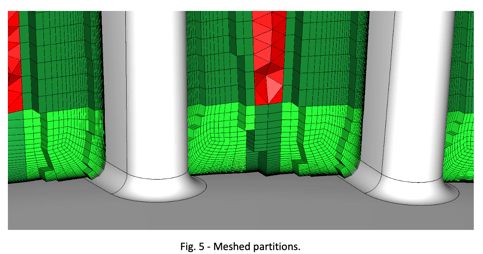 Fig. 5 shows an example mesh. The collar partitions (bright green) have been given a structured quad pattern. Using CADfix mapped meshing and division balancing, the pattern has a Y-shaped split in the center, and this pattern is swept through the collar partitions in a continuous loop. Where this mesh rests on the fillet faces, it remains independent of the face boundaries in the original model.
 Partitions resting on other model surfaces (dark green in Fig. 5) mesh with a structured or unstructured 2D meshing algorithm, and a volume mesh swept normal to the model surface.
The farfield, in this case, the narrow region remaining between the blades (red in Fig. 5), is meshed with a pyramid layer interfacing to tetrahedra.
Marine Propeller Examples: Propeller models are a fruitful application area for collar partitions since they often contain complex variable radius fillets and inclined leading/trailing edges that are challenging to mesh by other means.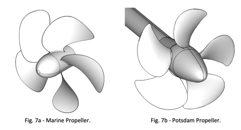 The propeller shown in Fig. 7a exhibits several challenges: the oblique departure of the blades from the hub, narrow sliver faces, and sharp face corner angles.
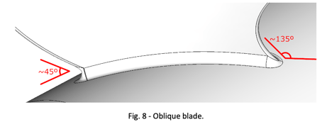
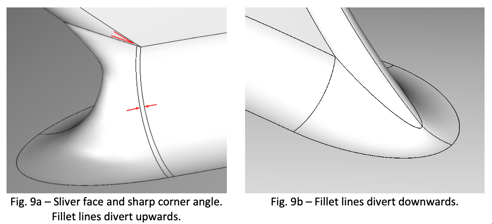
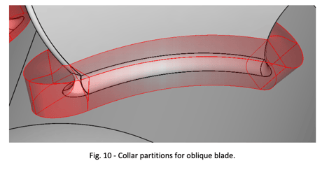
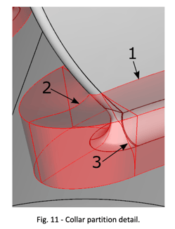 Fig. 11 shows the details of the partitioning around the sharp blade overhang: The profile of the collar where it meets the blade is determined by fitting a smooth surface to the medial halo loop and intersecting with the blade. This prevents malformed partition surfaces on the blade’s inclined leading/trailing edges where a perpendicular projection would be forced upwards. This fitted surface is shown in cyan in Figure 12, the medial halo loop in red.
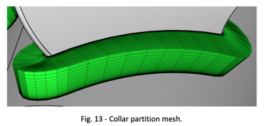
Since the attachment points for the collar have moved, the upright edges are curved to meet the model normal to the surface without moving the attachment point away from the chosen location.
The dividing walls between successive collar partitions are traced across the model surface, making them independent of the face boundaries in the CAD model, e.g. sliver faces are automatically suppressed.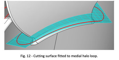
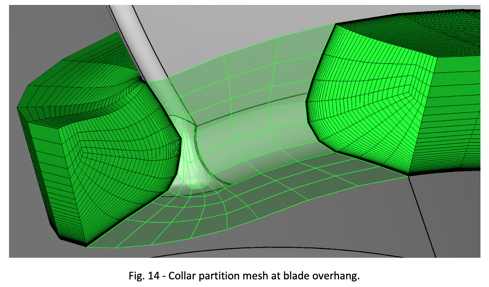
 Collar partitions can cover a larger region of the model beyond the small fillets and can be filled with fully structured mesh. This allows the swept boundary layer meshes in neighboring partitions to remain full height, without layer stopping or pullback.
The remaining partitions in this marine propeller example mesh with other CADfix meshing algorithms; for example, the main faces of the propeller blades are meshed with CGAP (Crossfield Guided Advancing Point), a quad-dominant 2D mesher, and then swept through the thickness.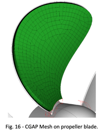
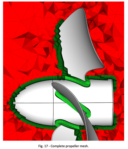
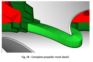 Fig. 17 shows a cross-section through the complete marine propeller mesh, with the collar partitions shown in full and the remaining mesh in cutaway view.
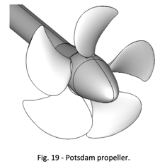
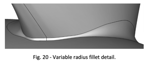
The Potsdam Propeller is another well-studied marine propeller model and features a similar arrangement of filleted blades. In this case, the fillets vary dramatically in radius, with the narrowest fillets presenting particular challenges to layer mesh growth. The detail in Fig. 20 shows the narrow fillet and misalignments in the CAD edge topology that defines the fillet face boundaries.
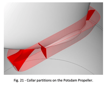 The collar partitions automatically encompass the whole fillet, a band of the hub/blade faces, and extend onto the nosecone at the front.
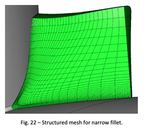
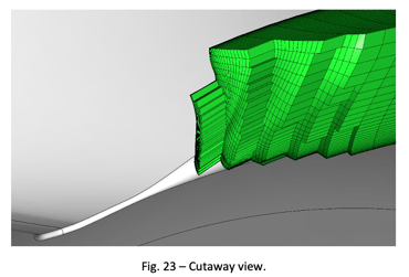 The cutaway view in Fig. 23 shows the mesh crossing over the fillet boundary edges, avoiding the need to stretch a quad grid out over the broader part of the fillet.
Conclusion: To summarise, we have demonstrated a fully automatic process for generating structured-dominant nearfield meshes for CFD applications. Using the Medial Object for insight into the shape of the fluid volume, CADfix partitioning offers a divide and conquer approach to mesh generation. The addition of automatic collar partitions makes the partitioning process applicable to a broader range of industrial models, with the ability to mesh across unwanted CAD face boundaries.
If you are interested in learning more about this development in CADfix, or other meshing challenges being tackled by CADfix, please contact ITI for more details.
Acknowledgments: Some of the results presented in this article were supported by the ATI/IUK project: COLIBRI
(TP number: 113296, Project number: 46349)