
Sunday June 11th sees the start of the NAFEMS World Congress in Stockholm, Sweden. The biennial international conference returns to Europe and promises to bring together engineers from across the analysis, simulation, modelling and systems engineering communities to present and discuss cutting-edge CAE technology. ITI will be present again this year, with engineers available on our exhibition stand and presenting a paper titled “Towards Fully Automatic Mid-Surface Meshing”.
The mid-surface approach has long been used in engineering to effectively simulate thin walled structures. Where traditional solid hexahedral meshes can be extremely time consuming to produce automatically for complicated structures, and automatically generated dense tetrahedral meshes require many more degrees of freedom and increase computation time, the mid-surface mesh approach can provide fast and efficient simulation results.
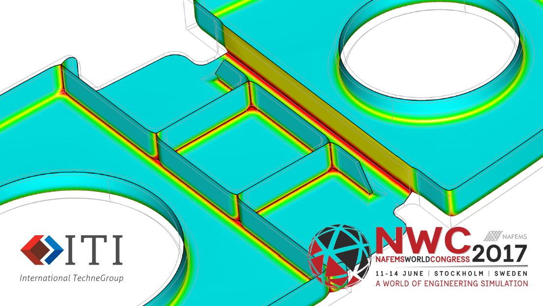
 Automatically generated complete mid-surface mesh of a complex CAD solid
Automatic generation of mid-surfaces has long been offered by some CAE software vendors, but methods usually rely on semi-automatic face pairing and intersection tests, and in some cases, use wholly manual methods to produce a mid-surface. These existing approaches are often time consuming and sometimes inappropriate for large models with complex filleted junctions and intersections.
ITI, in collaboration with industrial and academic partners has been developing technology to support fully automatic, accurate and robust mid-surface generation.
Automatic Mid-surface using MO Technology
The Medial Object (MO) has a wide range of applications in CAE, and provides a rich source of data about the definition of boundary representation (BREP) CAD solids. Automatically generating the MO is the first step to generating the mid-surface of a BREP model. The MO provides non-manifold geometry which is close to the required mid-surface. The complete MO contains artefacts or “flaps” that occur as the MO radius reduces to zero in corners. These “flaps” are identified, removed and the exposed edges are then extended out to the BREP geometry boundary. Finally, the mid-surface is converted to analytic or NURBs surfaces ready for automatic shell meshing and simulation.
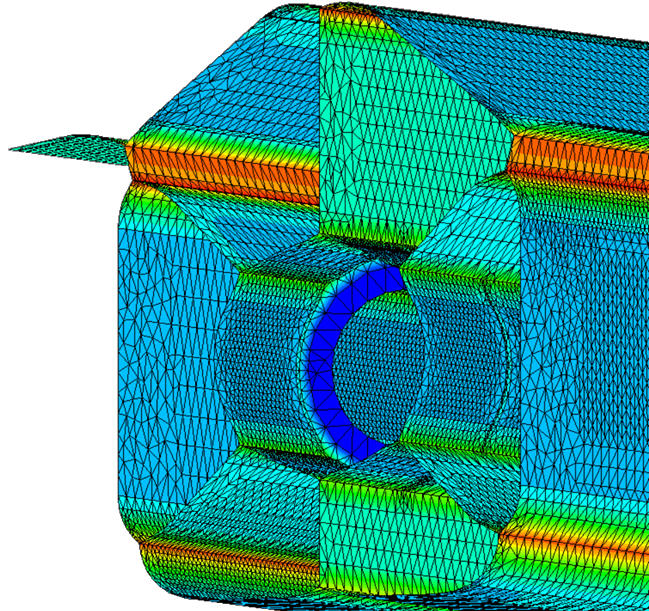
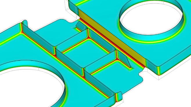
Close-up of a T-Junction, meshed and ready for simulation (colours indicate thickness shell element attributes derived from the MO)
Complex Real World Mid-surface
The following example is a complex aircraft rib that has been run through the CADfix prototype mid-surface generation tool. The MO based method only takes a few minutes to generate a complete mid-surface suitable for meshing.
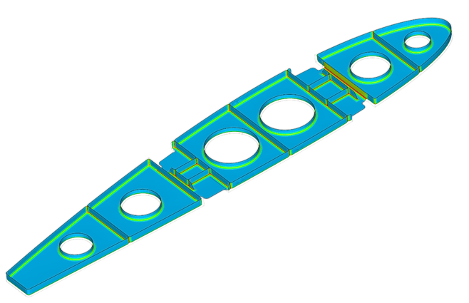 Complete Mid-surface of an aircraft rib.
 Close up of the aircraft rib mid-surface.
Resolving Intersections and Junctions
Most mid-surfaces represent complex junctions as a straight intersection between two planar surfaces. Using the MO, we can generate junctions and intersections which more accurately reflect the geometry of the BREP, especially in regions of variable radius filleting and different material thickness. MO based T-junctions contain “cusps” that respect the increasing or decreasing size of the medial sphere in these junctions. When the MO based mid-surface method is discussed, engineer’s biggest reservations are often that these regions containing cusps are unacceptable and could lead to significant errors.

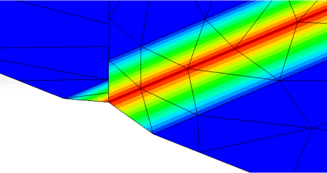
Different possible T-junction cross-sections. Which is "correct"?
Numerical Simulations of Mid-surfaces
ITI teamed up with Bob Johnson of Realistic Engineering Analysis Limited to run some experimental numerical simulations, comparing the results of full, accurate solid meshes with MO-derived mid-surface meshes which include cusped junctions that accurately represent the true geometrical mid-surface.
Comparative analyses have demonstrated that these accurate, MO-based mid-surface meshes with their cusped T-junctions, are not only reliably accurate, but they represent filleted junctions better than the traditional, straight T-junctions.
The full results of our analysis will be discussed in full at the NAFEMS World Congress and will be available in the conference proceedings.
Conference Exhibition
As well as presenting a paper, ITI’s Andy Chinn and Claire Pollard will be present throughout the conference on exhibition stand 10 to discuss ITI’s solutions for the engineering simulation community. Hope to see you there.
If you would like to find out more about the prototype Mid-surface generation tool featured here, please get in touch with our team: