
Today sees the launch of the latest version of ITI’s leading CAD model repair, translation and simplification tool CADfixTM.
CADfix has an established history in providing a rich set of tools that help engineers in all industry sectors get the most out of their geometry across a range of CAD, CAM and CAE applications, neatly complementing existing systems, and with the ability to import and export model data from a wide range of formats.
In this latest blog article, we explore the new tools available in CADfix 12 and look at their diverse applications and use cases.
Visualisation and Digital Mock-Up
Increasingly product designers and engineers are turning to virtual reality (VR) or augmented reality (AR) for visualising their product designs. Traditional 3D CAD BREP geometry with its inherent detail is often unsuitable for VR and similar systems that require lightweight model representations for rapid animation and manipulation.
To address this, CADfix 12 now supports the export of lightweight faceted model representations to the FBX, OBJ, XGL and ZGL formats with the ability to export assemblies, colours, transparency, vertex normals for smooth shading and level of detail options to control the facet count of the exported model. This enables users to produce compact but appropriately detailed model representations which are perfectly suited to the VR/AR environment.
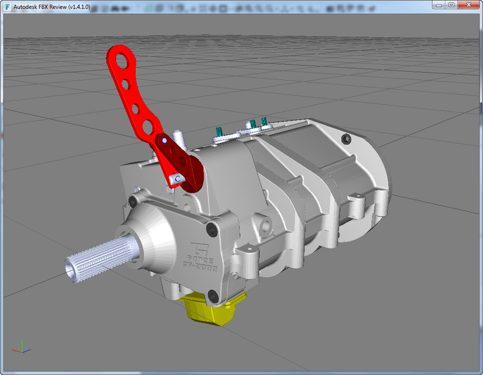
Export via FBX to Autodesk FBX review
Macro Record and Playback
With an extensive API to enable users to script their CAD simplification process, CADfix has always had a focus on enabling CAD repair and defeaturing as part of an automated workflow. However, the writing of batch scripts used to require users to be familiar with the underlying CADfix command language and APIs.
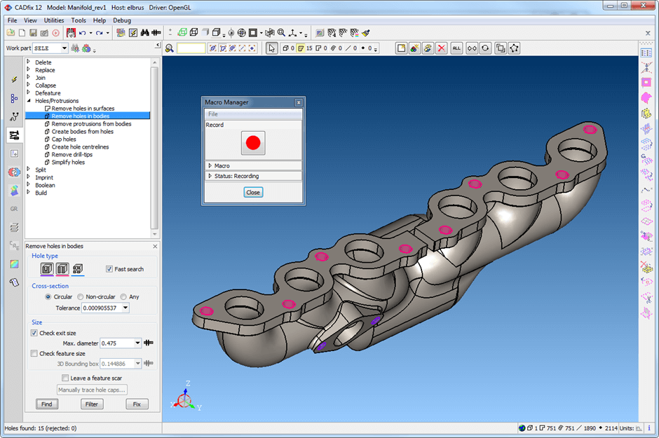
With the new CADfix 12 Macro Record and Playback tool, the power of scripting has been brought into the GUI, enabling users to record any series of interactive operations on a model and replay them, either on the same model, or on different models requiring similar clean-up, either in an interactive CADfix session or as part of a batch run. The playback of recorded macros also offers the ability to step through a macro and check the effect on the model at each step. The user can also edit a saved macro and insert additional actions at any point.

Macro Record and Playback for repeating complex workflows automatically
A common problem with recording macros that operate on specific user selected named entities is they can often fail when played back on a different model that does not contain exactly the same named entities. However, a CADfix macro that references such user selected entities can be replayed on models with different entity names. This unique capability uses an automatic 3D comparison between the recorded model and the current model, enabling it to identify similar entities by their geometrical definitions and hence map the entity names between models when playing back the macro.
The new macro record facility in CADfix 12 allows users to easily build and repeat model processing workflows with ease and apply them across the whole lifecycle of a CAD model.
3D Diff tool
Throughout the lifecycle of a product designs can be repeatedly worked on by different engineers, sometimes across multiple departments and even external companies. It is important to be able to quickly identify changes and inconsistencies between different CAD models and any derived simulation mesh data throughout these engineering processes. CADfix 12 introduces three new tools for use in the CAD, CAE, simulation and advanced manufacturing sectors, that will enable users to quickly and easily identify differences between CAD models and mesh data.
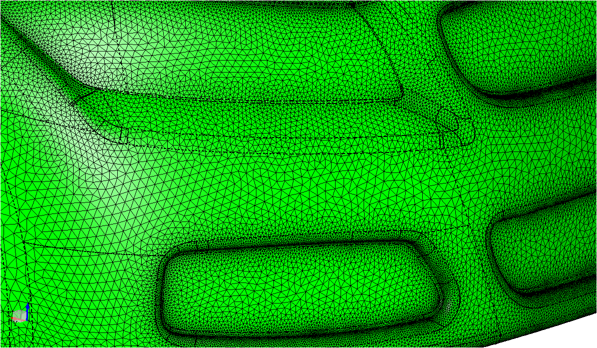
Firstly, the Mesh to CAD comparison tool can compare a CAD model to a corresponding CAE mesh, which is essential for verifying that the mesh accurately captures the CAD geometry for simulation and modelling purposes. Surface and volume meshes from a range of formats can be imported. For volume meshes the skin of the solid elements is extracted for comparison to the CAD model. The comparison tool reports the maximum difference detected between mesh and CAD, and helpfully highlights the maximum regions. Where the mesh does not match the CAD geometry, such as when the mesher ignored or supressed certain edges or faces, then CADfix can detect the unmatched entities and visually highlight them to the user for inspection. The matching process has also been optimised to handle very large meshes efficiently, providing the user with a vital quality check on their simulation mesh.
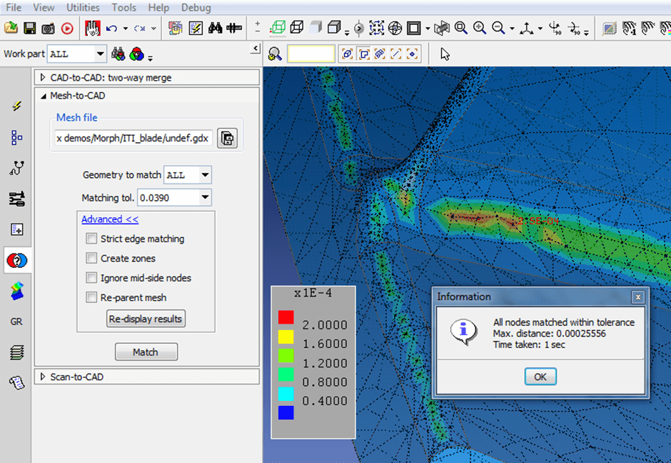
Mesh to CAD comparison showing the accuracy of the mesh
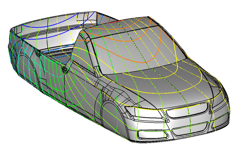
The second new diff tool in CADfix 12 provides a new CAD to CAD 3D differencing capability that allows users to quickly identify changes between a pair of CAD models, for example two versions from a design process, and then to construct a new hybrid CAD model by merging selected features from each. This comparison and merging technique enables engineers to retain simplified features from an earlier CADfix defeaturing session whilst merging in selected new features from the latest design, dramatically shortening the time taken to prepare an updated model for analysis.
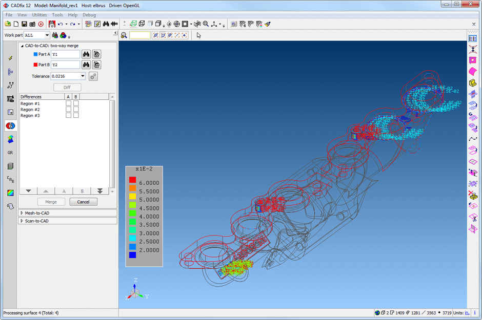
The CAD to CAD differencing tool can be used to compare and merge geometries
Finally, a 3D scan to CAD tool is also available to detect differences between the as-designed CAD part and the as-manufactured part, captured from a 3D scan. STL and PLY formats are supported for importing scan data. The tool detects and highlights the regions of maximum distance between scan and CAD, providing the user with valuable feedback on the accuracy of the manufactured part.
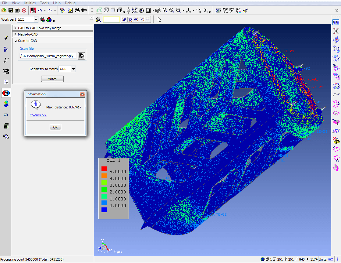 The Scan to CAD differencing tool highlighting regions of maximum difference
Geometry Morphing
Following a CAE simulation, CAD rework is often needed to adjust the CAD model based on the results from analysis. This manual rework can be time consuming and often requires CAD models to approximate the simulation results or be built from scratch by hand, with limited reuse of the original model geometry.
The CADfix geometry morphing tool allows users to automatically morph existing CAD model geometry to accurately match a displacement field from simulation, using a pair of meshes, one which matches the original CAD and one which matches the deformed simulation data, for example a hot running shape of a turbine blade derived from a thermo-mechanical analysis.
Generating new morphed geometry using a deformed mesh from analysis.
Using intelligent mesh and geometry matching, CADfix can generate a new CAD model by morphing the original CAD using the displaced mesh as a deformation guide. This process automatically provides the user with new BREP CAD geometry matching the deformed mesh shape, ready for export to further CAD or simulation processes.
Complex Zone Parameterisation
Modern CAD systems often provide challenging geometry for mesh generation tools. With small sliver surfaces, fillets and detailed geometrical features, meshers are often forced refine their grids in these regions leading to wastefully dense meshes with inconsistent element sizing across these areas of constraining geometry.
One solution is to defeature the model, removing or collapsing features, or joining small sliver surfaces to neighbours, but often the resulting geometry that is used for simulation is different from the actual design, which can lead to results that aren’t wholly representative of the engineer’s original intent.
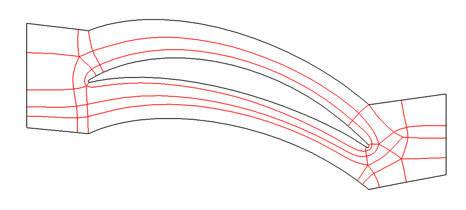
Zone parameterisation across a complex set of surfaces.
That’s where the CADfix 12 Complex Zone Parameterisation tool steps in. The tool allows users to parameterise models across existing geometric face boundaries allowing a regularly sized mesh to be placed across these awkward surfaces whilst accurately capturing the underlying surface geometry.
Meshing across surface edges using a zoned parameterisation
New Defeaturing Technologies
Existing tools in CADfix allow you to remove different features from a CAD model which aren’t required for the next stage in your design or manufacturing process. Features such as fillets, chamfers, small bodies and internal features can all be removed using the established CADfix tools.
CADfix 12 sees two new tools that provide novel ways to prepare geometry for meshing.
Cross-field based quad splitting
Quad meshing of surfaces is commonplace in the meshing community, but for complex face definitions created by modern CAD systems, obtaining a high quality quad mesh can be problematic. By subdividing a complex face into smaller quadrilateral faces, meshing systems can more easily place a regular quad grid in these smaller faces, maintaining a higher quality of mesh across the entire face. The new CADfix 12 “Split faces into quads” tool automates the process of robustly identifying suitable regions and splitting a CAD face into quad patches for meshing.
 Quad subdivision of a complicated surface ready for meshing
Hex-skin partitioning tool for hybrid meshing
Moving from structured surface to structured volume meshes, the automatic hex-skin tool allows users to automatically partition a model, using ITI’s CADfix 3D Medial Object Technology, into regions suitable for producing a structured hex mesh layer close to the surface and an unstructured tet-mesh elsewhere.
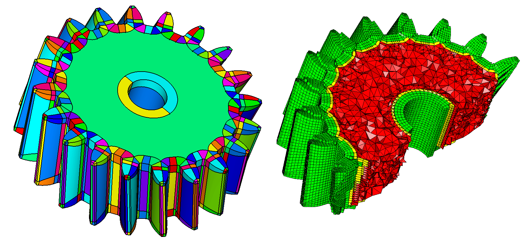 Auto hex-skin subdivision and hybrid meshing
The hex-skin approach to meshing means that singularities are not propagated through a mesh, as they can be in fully structured hex mesh volumes, and it allows for appropriate mesh sizing close to the boundary. This technology was recently presented at the NAFEMS UK Conference and has benefited from developments as part of ongoing Innovate UK and industrial research projects.
Other features
- Roll up of service packs from CADfix 11 SP1 and CADfix 11 SP2
- New GUI layout
- Performance boost across most tools with a 3-5 times speed increase over CADfix 11
In forthcoming blogs, we will focus on more of the latest CADfix tools in more detail.
CADfix 12 is available now. If you have any questions, or want to get in touch please use the button below.