Today sees the launch of Service Pack 1 for ITI’s CADfix 11, the leading software solution for CAD model translation, repair, defeaturing and simplification, and the generation of clean models for use in diverse downstream CAD, CAM and CAE applications.
Service Pack 1 upgrades the CADfix native CAD interface support for systems including NX11, Creo 4 and Solidworks 2017, along with improvements to most of the other CADfix native and neutral format interfaces. Service Pack 1 also sees the addition of new features and tools to the already extensive CADfix geometry handling toolset.
New DXF/DWG Assembly Support
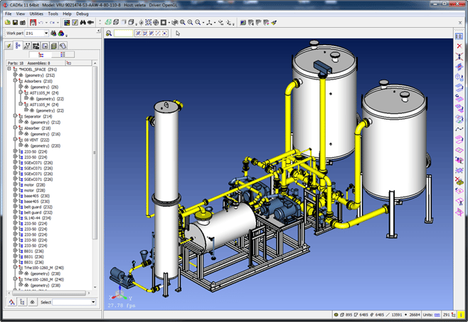
CADfix 11 SP1 introduces support for DXF/DWG assembly files, leading to much faster model processing times and the export of significantly smaller geometry files. We recently held a webinar to demonstrate the power of using CADfix to automatically simplify large complex CAD assemblies before integration into Plant and Process design systems - an application area that will see significant file size reductions and productivity improvements as a result of the new DXF/DWG assembly support.
Improved Defeaturing
CADfix offers a large suite of CAD model defeaturing tools that enable users to remove features from CAD models that might otherwise hamper their downstream applications. One defeaturing tool in particular has seen improvement since the release of CADfix 11 last September. The fillet removal tool can now handle split fillets and complicated junctions between multiple fillets with a significantly higher success rate thanks to a new incremental algorithm.
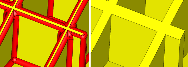
Complex split fillets and problematic junctions can be handled with the new incremental algorithm in CADfix 11 SP1
3D Printing Capabilities
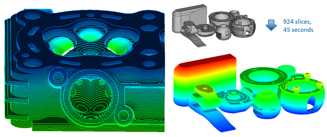
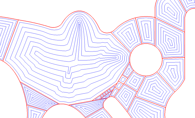
CADfix 11 SP1’s curved facet slicer generates more accurate slices faster.
Since completing the Hyproline project and starting the Symbionica project, we have seen an increased need for reliable and innovative slicing of 3D CAD model geometry for additive manufacturing. The CADfix slicer now has improved capabilities using curved facets to better match the geometry being sliced. Along with curved slices, a robust method for detecting multiple loop slices has been added to reduce the failures when generating slices containing holes or other internal CAD features. These new additions to the slicing algorithm also benefit from parallelisation of the slicer, which ultimately results in highly accurate slices being generated considerably faster than in previous versions of CADfix. A new prototype hatching tool also allows CAM users to generate variable radius toolpaths based on our Medial Axis Transform technology, that can be exported to a CL file for downstream use.
Shrink-wrapping and Automatic Mid-surfacing
There are two new prototype tools available in CADfix 11 SP1; a new version of the shrink-wrapper and an automatic mid-surfacing tool.
Shrink-wrapping
Since the initial release of CADfix 11, we’ve been working on an alternative to the traditional oct-tree based shrink-wrapping algorithms. Our newly released shrink-wrap process has a robust method for capturing thin regions and sharp edges, for example on trailing edges and junctions of aerospace models, and an option to recover the CAD parency enabling quality re-meshing using complex size controls. The high level of automation means that it requires significantly less user input and cleanup to get a usable wrap first time. The new prototype shrink-wrap tool will continue to be developed by our team with an aim to be fully productionised in CADfix 12.
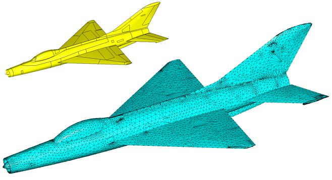
Top left: Original geometry, Bottom right: CADfix 11 SP1 Shrink-wrapped
Automatic Mid-surfacing
Automatic mid-surfacing has long been claimed by other products, but there has always been some manual intervention needed to complete the mid-surface geometry in anything but the simplest of cases. Our new prototype automatic mid-surface tool in Service Pack 1 provides a high level of automation and reduces the need for user intervention. Starting from the solid CAD model geometry, CADfix can generate either new BREP mid-surface geometry or a mid-surface mesh containing thickness attributes derived from the source 3D model. Using the 3D Medial Object, CADfix’s mid-surface represents the true mid-surface through a solid body, taking into account complex junctions and variable thicknesses across a solid. We will be presenting a paper on this new technology at this year’s NAFEMs World Congress in Stockholm on the 11th of June 2017.
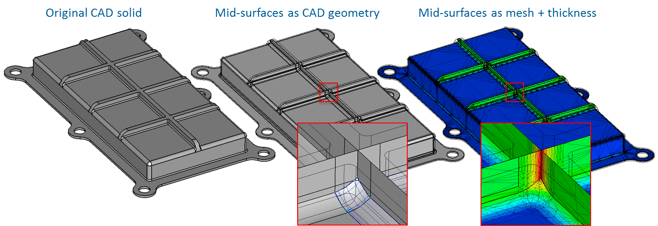
Mid-surfaces can be automatically generated from CAD solids in CADfix 11 SP1
 for more information on CADfix 11 Service Pack 1 and how it can help you improve your interoperability processes.

